Tutorial (Raspberry Pi Mouse, RTM Seminar)
Tutorial (RTM Seminar, Windows, Part 2)
Introduction
This page describes the procedure for creating components for operating the Raspberry Pi mouse on the simulator.
Downloading materials
Please download the materials first.
- [[RTM_Tutorial.zip:https://github.com/OpenRTM/RTM_Tutorial/archive/master.zip]
Please unarchives ZIP file by tools such as Lhaplus.
The seminar may be held in an environment where you cannot connect to the Internet. In that case, it is stored in the distributed USB memory.
Simulator
The simulator is developed using a physics engine called Open Dynamics Engine (ODE): http and a drawing library (drawstuff) that comes with ODE. It works if OpenGL works, so it should work in most environments.
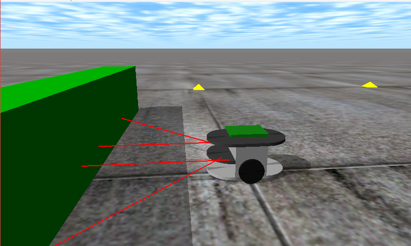
You can simulate the following robot Raspberry Pi mouse.
Not only the dynamic calculation and contact response of the Raspberry Pi mouse on the simulator, but also the data of the distance sensor reproduces the values close to those of a real robot.
Raspberry Pi mouse specifications
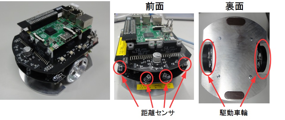
The Raspberry Pi mouse is an independent two-wheel drive mobile robot sold by RT corp..
| RaspberryPi Mouse Specification | |
| CPU | Raspberry Pi 2 Model B |
| Motor | Stepping motor ST-42BYG020 x2 |
| Motor Driver | SLA7070MRPT x2 |
| Distance sensor | Red LED + Photo-transistor(ST-1K3) x4 |
| Monitor red LEDs | x4 |
| Buzzer | x1 |
| Tact switch | x3 |
| Battery | LiPo3-cells (11.1V) 1000mAh x1 |
RT-Component to be developed
- RobotController Component
An RT-Component to control the robot on the simulator by connecting with the RaspberryPiMouseSimulator Component.
Creating the RobotController Component
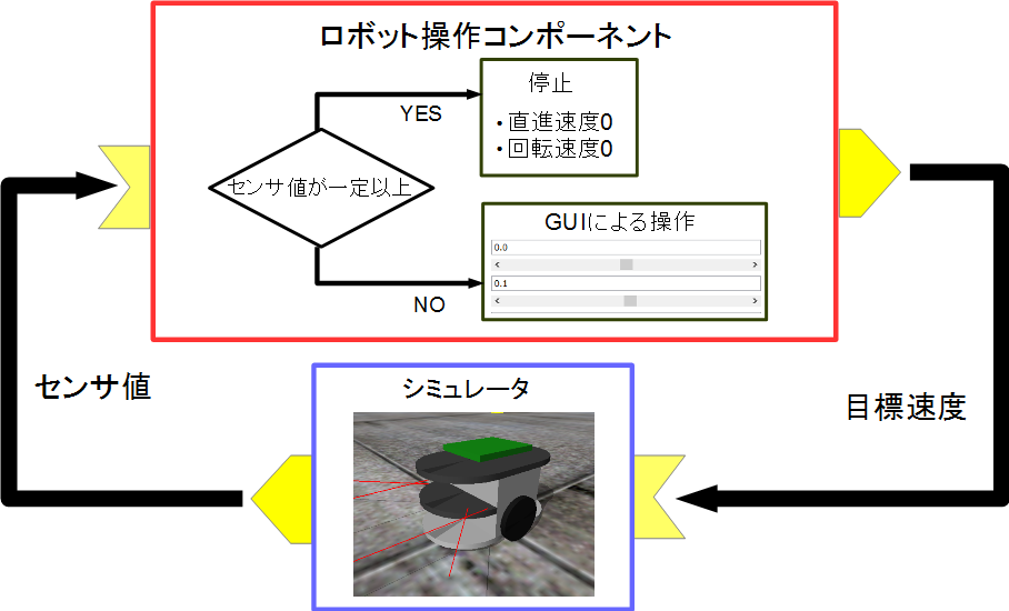
An RT-Component which can operate the robot on the simulator with the GUI (slider) and automatically stops when the sensor value exceeds a certain level will be created.
Development process
The development process is as follows.
- Confirmation of development environment
- Determine component specifications
- Creating a source code template with RTC Builder
- Edit source code
- Checking the operation of components
Confirmation of development environment
The following development environment is assumed.
- OS: Windows 10
- OpenRTM-aist: 1.2.1
- Visual Studio: 2019:(2013、2015、2017 are also OK)
- CMake:recommend version 3.5 or higher
- Python 2.7
- Doxygen
RT-Component's specification
The RobotController has an OutPort that outputs the target speed, an InPort that inputs the sensor value, and configuration parameters that set the target speed and the sensor value to stop.
| Name of RT-Component | RobotController |
| InPort | |
| Name of InPort | in |
| Type | TimedShortSeq |
| Description | Sensor value |
| OutPort | |
| Name of OutPort | out |
| Type | TimedVelocity2D |
| Description | Target velocity |
| Configuration | |
| Name of configuration parameter | speed_x |
| Type | double |
| Default value | 0.0 |
| Constraints | -1.5<x<1.5 |
| Widget | slider |
| Step | 0.01 |
| Description | The speed of straight-ahead |
| Configuration | |
| Name of configuration parameter | speed_r |
| Type | double |
| Default value | 0.0 |
| Constraints | -2.0<x<2.0 |
| Widget | slider |
| Step | 0.01 |
| Description | The rotational speed |
| Configuration | |
| Name of configuration parameter | stop_d |
| Type | int |
| Default value | 30 |
| Description | The sensor value to be stopped the robot |
About TimedVelocity2D type
We use the TimedVelocity2D type, which is a data type that stores the moving speed of a moving robot on a two-dimensional plane.
     struct Velocity2D
     {
           /// Velocity along the x axis in metres per second.
           double vx;
           /// Velocity along the y axis in metres per second.
           double vy;
           /// Yaw velocity in radians per second.
           double va;
     };


     struct TimedVelocity2D
     {
           Time tm;
           Velocity2D data;
     };
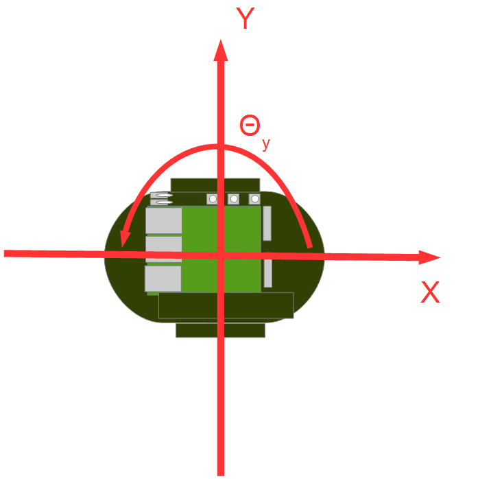
This data type can store the velocity vx along the X axis, the velocity vy along the Y axis, and the velocity va around the Z axis.
vx、vy、va represents the velocity in the robot center coordinate system.
vx is the velocity in the X direction, vy is the velocity in the Y direction, and va is the angular velocity around the Z axis.
For a robot with two wheels mounted on the left and right, such as a Raspberry Pi mouse, vy would be 0 assuming no skidding.
The robot is operated by specifying the straight-ahead speed vx and the rotation speed va.
About distance sensor data
The data of the distance sensor of the Raspberry Pi mouse is designed to output a larger value as the distance to the object gets closer.
| Value from sensor | Actual distance[m] |
| 1394 | 0.01 |
| 792 | 0.02 |
| 525 | 0.03 |
| 373 | 0.04 |
| 299 | 0.05 |
| 260 | 0.06 |
| 222 | 0.07 |
| 181 | 0.08 |
| 135 | 0.09 |
| 100 | 0.10 |
| 81 | 0.15 |
| 36 | 0.20 |
| 17 | 0.25 |
| 16 | 0.30 |
The simulator reproduces this value and outputs it. The RobotController component implements a process that automatically stops when this value exceeds a certain level.
RobotController component template generation
RTCBuilder is used to generate the template for the RobotController component.
Start RTCBuilder
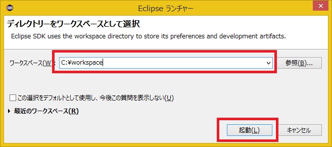
In Eclipse, the folder where you do various tasks is called a "workspace", and as a general rule, all products are stored under this folder. You can create a workspace in any folder that you can access, but this tutorial assumes the following workspace.
- C:\workspace
First, start Eclipse. For Windows 10, you can start it by clicking Start menu> "OpenRTM-aist 1.2.1"> "OpenRTP", or search OpenRTP from the search window in the next of the Start Button.
You will first be asked for the location of the workspace, so specify the workspace above.
Then, the following Welcome page will be displayed.
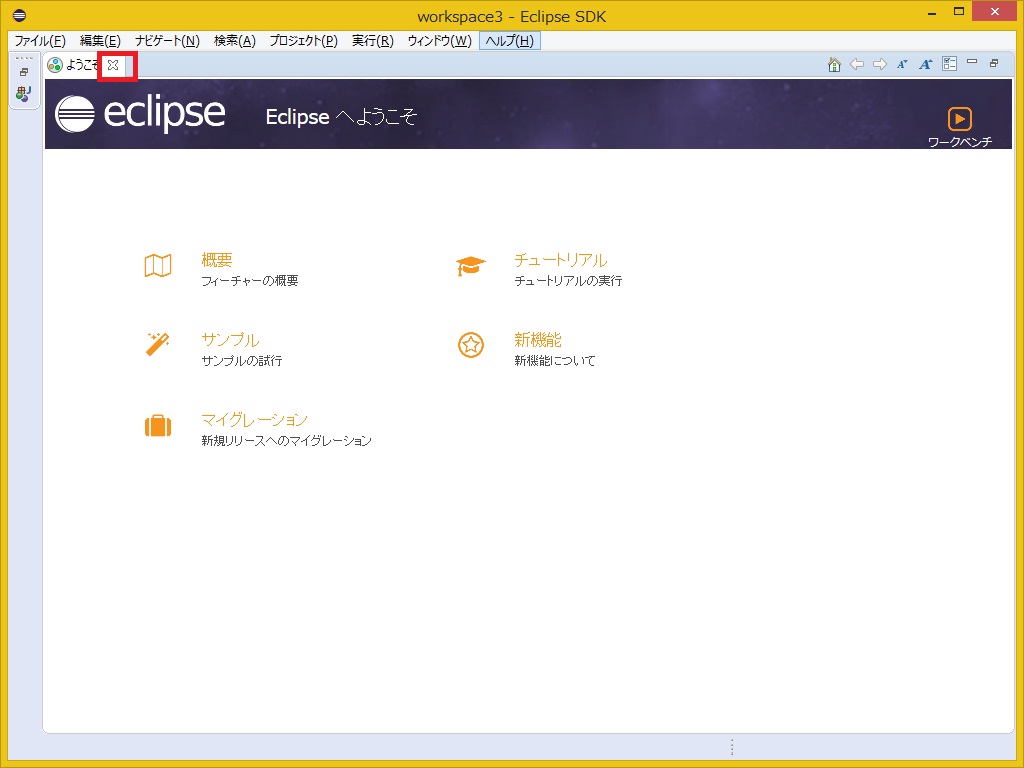
The Welcome page is no longer needed, so click the x button in the upper left to close it.
Click the [Open Perspective] button in the upper right.
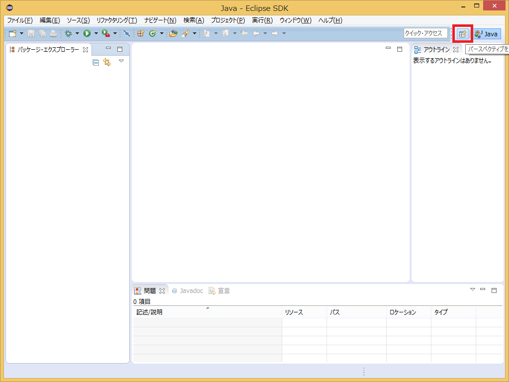
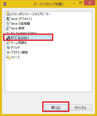
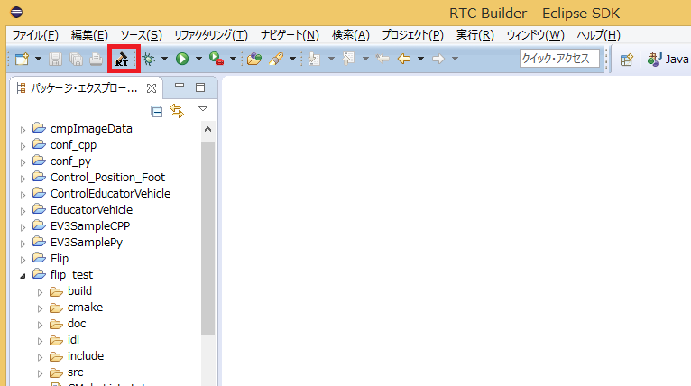
Select RTC Builder to start RTC Builder. The RTCBuilder icon for Hammer and RT appears in the menu bar.
Create a new project
You need to create a new project in RTCBuilder to create the RobotController component.
Click the Open New RTCBuilder Editor icon in the upper left.
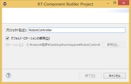
Enter the project name (here, RobotController) to be created in the Project Name field and click the [Finish] button.
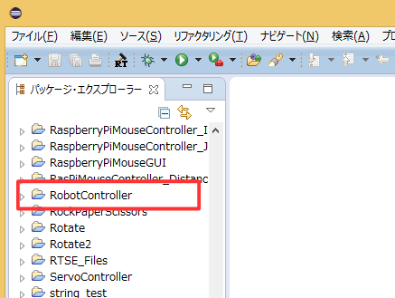
A project with the specified name will be generated and added to the Package Explorer.
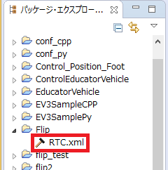
The RTC profile XML (RTC.xml) with default values is automatically generated in the generated project.
Launch RTC Profile Editor
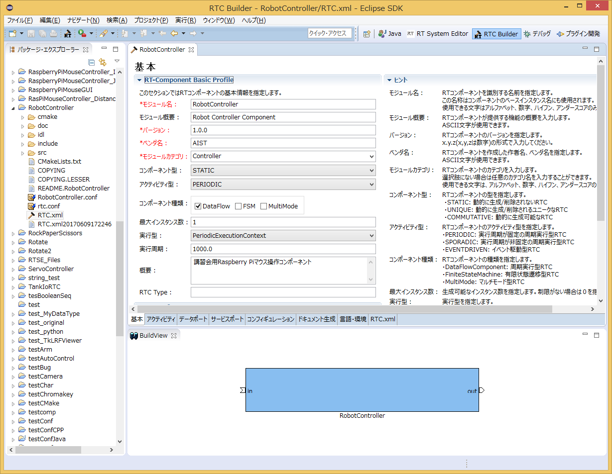
When RTC.xml is generated, the RTCBuilder editor should open as the workspace associated with this project. If it doesn't start, double-click RTC.xml in Package Explorer.
Profile information input and code generation
First, select the Basics tab on the far left and enter the basic information. In addition to the RobotController component specifications (name) you decided earlier, enter the outline, version, etc. Items with red labels are required items. Others can be the default.
- Module name: RobotController
- Module description: Any (Robot Controller component)
- Version: Any (1.0.0)
- Vendor name: Any
- Module category: Any (Controller)
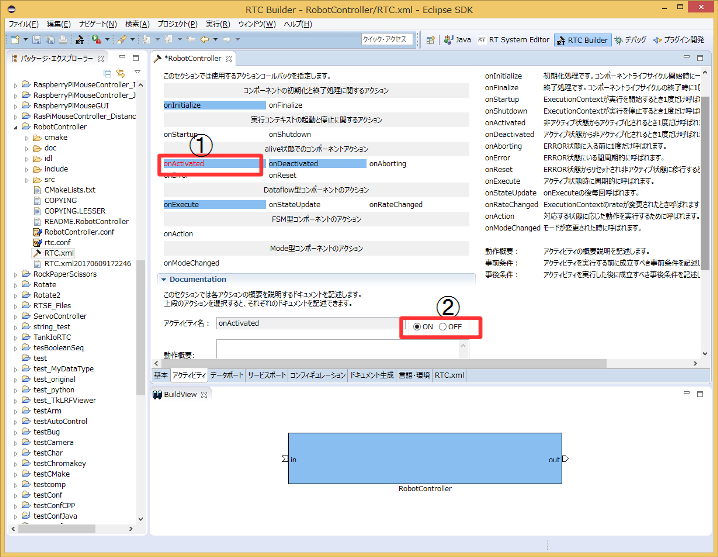
Then select the Activity tab and specify the action callback to use.
For RobotController component uses the onActivated(), onDeactivated(), onExecute() callbacks. As shown in the figure below, after clicking onAtcivated in (1), check [ON] with the radio button in (2). Just double-clicking the onActivated label toggles [ON] and [OFF]. Follow the same procedure for onDeactivated and onExecute.
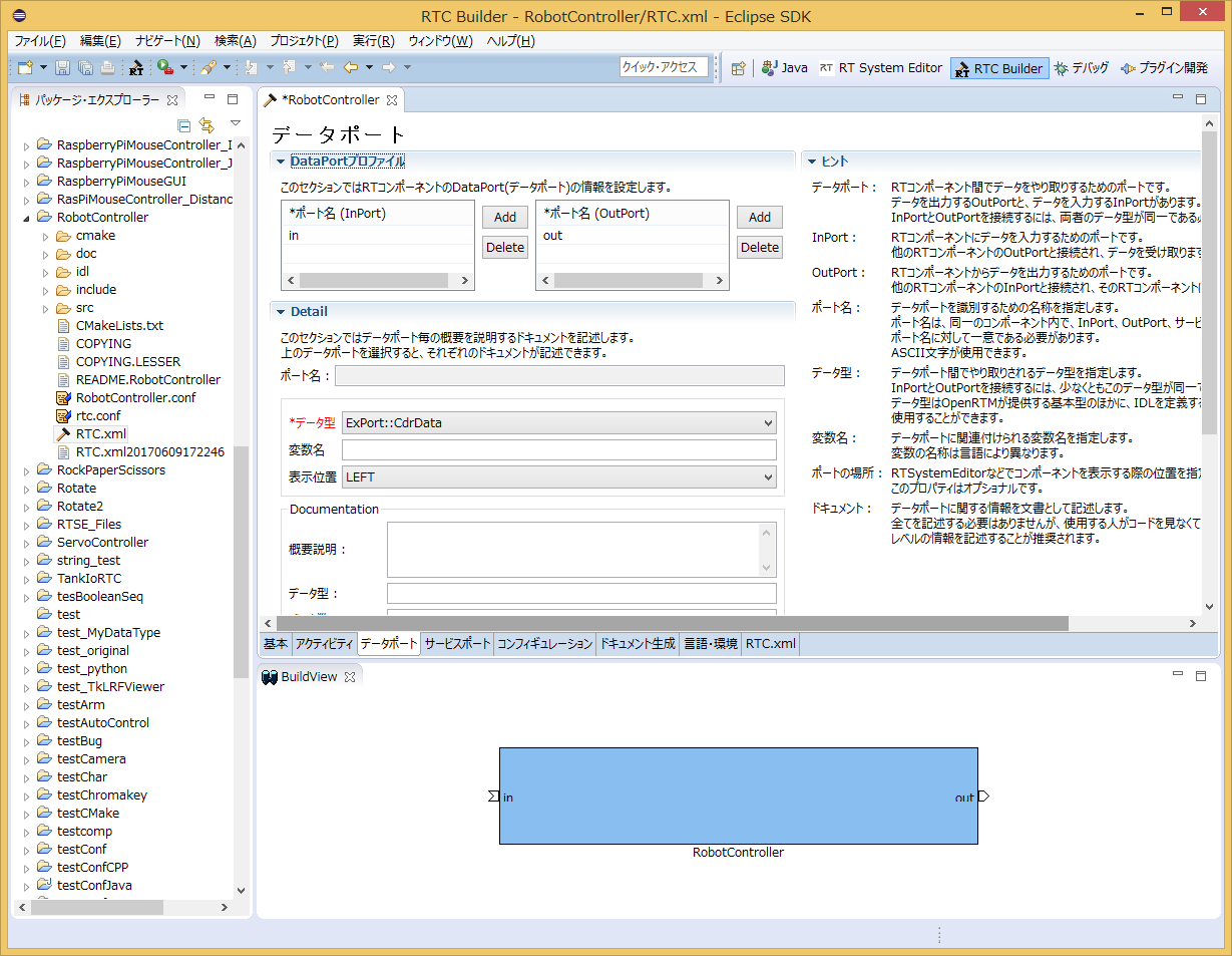
In addition, select the DataPort tab and enter the DataPort information. Enter the following based on the specifications you decided above. The variable name and display position are optional and can be left as they are.
- InPort Profile:
- Port name: in
- Data type: TimedShortSeq
- OutPort Profile:
- Port name: out
- Data type: TimedVelocity2D
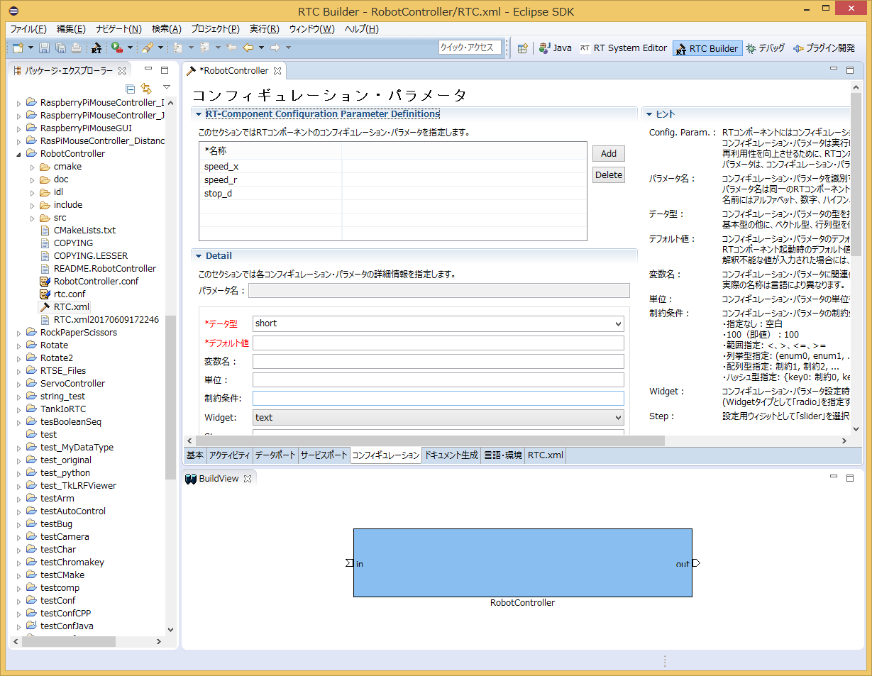
Then select the Configuration tab and enter the Configuration information based on the specifications you just decided. Constraints and widgets are used to change values in the GUI, such as sliders, spin buttons, and radio buttons, when displaying component configuration parameters in RTSystemEditor.
The straight speed speed_x and the rotation speed speed_r make it easier to operate with the slider.
- speed_x
- Name: speed_x
- Data type: double
- Default value: 0.0
- Constraints: -1.5<x<1.5
- Widget: slider
- Step: 0.01
- speed_r
- Name: speed_r
- Data type: double
- Default value: 0.0
- Constraints: -2.0<x<2.0
- Widget: slider
- Step: 0.01
- stop_d
- Name: stop_d
- Data type: int
- Default value: 30
- Widget: text
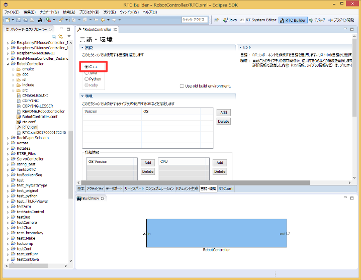
Next, select the Language / Environment tab and select the programming language. Here, select C++ (language). In addition, defaults etc. are not set for the language and environment, and if you forget to specify it, an error will occur at the time of code generation, so be sure to specify the language.
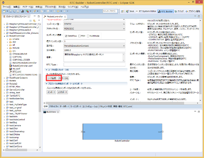
Finally, click the Generate Code button on the Basic tab to generate a template for the component.
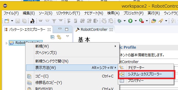
You can open the workspace in Explorer by right-clicking on the project and selecting View> System Explorer.
Generating the files needed to build with CMake
The code generated by RTCBuilder includes CMakeLists.txt to generate various files required for building by CMake. By using CMake, Visual Studio project files, solution files, Makefiles, etc. can be automatically generated from CMakeLists.txt.
Operation of CMake (cmake-gui)
Use CMake to configure the build environment. First, start CMake (cmake-gui). You can start it by clicking Start button> App View (lower right arrow)> CMake X.Y.X> CMake (cmake-gui), or search with cmake-gui from the search window next to the start buttont.
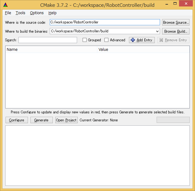
There are the following text boxes at the top of the screen, so specify the source code location (where CMakeList.txt is) and the build directory, respectively.
- Where is the soruce code
- Where to build the binaries
The source code location is where the RobotController component source was generated and where CMakeList.txt resides. The default is <workspace directory>/RobotController.
This directory is set by dragging and dropping from Explorer to cmake-gui without any manual input.
The build directory is the place to store project files, object files, and binaries for building. The location is arbitrary, but in this case it is recommended that you specify a subdirectory of RobotController with a descriptive name, such as <workspace directory>/RobotController/build.
| Where is the soruce code | C:\workspace\RobotController |
| Where to build the binaries | C:\workspace\RobotController\build |
Once specified, click the Configure button below. Then a dialog like the one below will be displayed, so specify the type of project you want to generate. This time, let's call it Visual Studio 16 2019. If you are using Visual Studio 2013 or Visual Studio 2015, please change it. Also set the platform to x64. If you have installed the 32-bit version, select Win32.
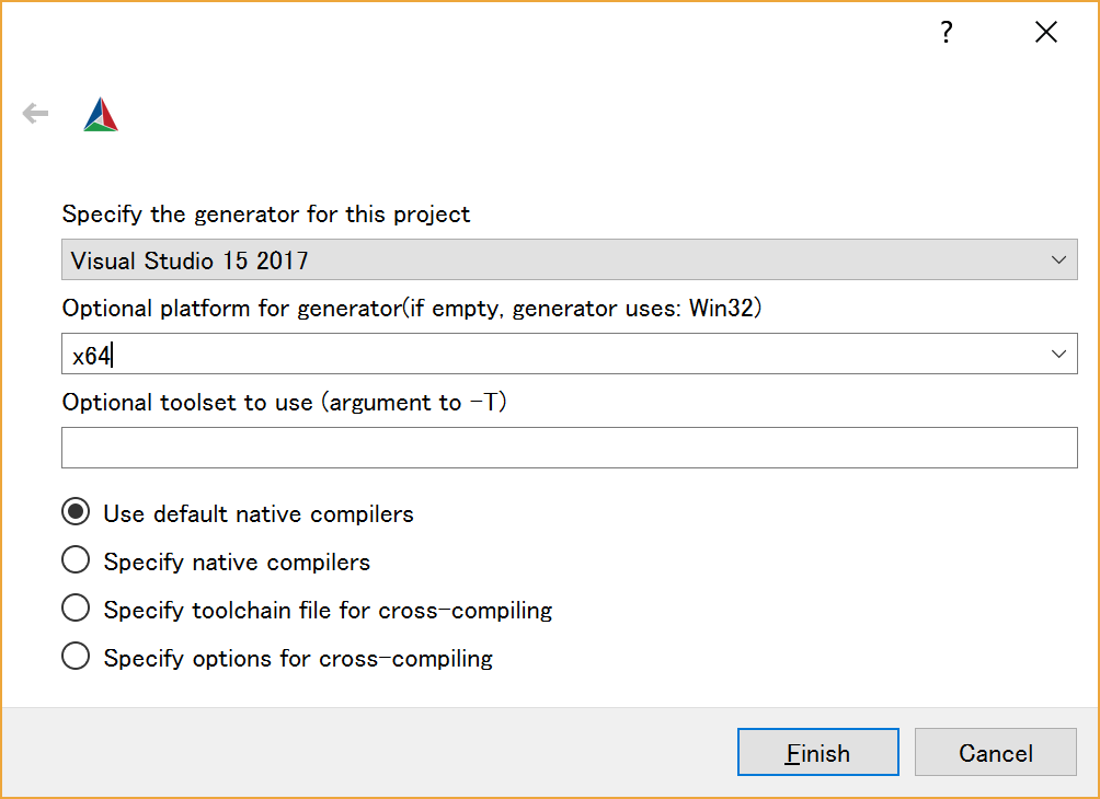
Click the [Finish] button in the dialog to start Configure. If there are no problems, Configuring done will be output in the log window at the bottom, so click the [Generate] button. If Generating done is displayed, the output of the project file, solution file, etc. is completed.
Note that CMake generates a cache file at the stage of Configure, so if you change the settings or change the environment due to trouble etc., delete the cache with [File]> [Delete Cache] and start over from Configure.
Editing headers and sources
Then double-click RobotController.sln in the build directory you specified earlier to start Visual Studio.
NOTE: In the new version of cmake-gui, you can start it by clicking the button on cmake-gui.
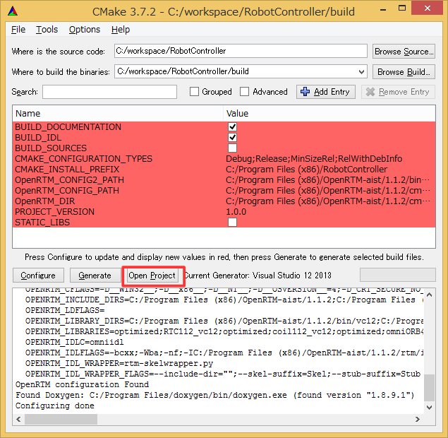
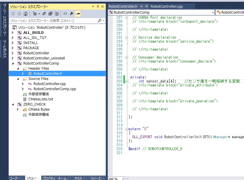
Edit the header (include/RobotController/RobotController.h) and the source code (src/RobotController.cpp) respectively. Click RobotController.h, RobotController.cpp from the Solution Explorer of Visual Studio to open the edit screen.
Implementation of activity processing
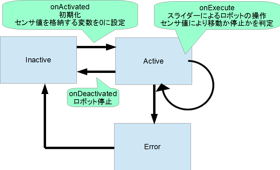
In the RobotController component, the configuration parameters (speed_x, speed_y) are operated with sliders and the values are output from the outport (out) as the target speed. The value input from import (in) is stored in the variable, and if the value exceeds a certain value, it stops.
The following figure shows the processing contents of onActivated(), onExecute(), and onDeactivated().
Editing the header file (RobotController.h)
Declare the variable sensor_data to temporarily store the sensor value.
   private:
      int sensor_data[4];    // A variable that stores the sensor value
Editing the source file (RobotController.cpp)
Implement onActivated(), onDeactivated(), onExecute() as shown below.
 RTC::ReturnCode_t RobotController::onActivated(RTC::UniqueId ec_id)
 {
         // Initialize sensor vaiables
         for (int i = 0; i < 4; i++)
         {
                 sensor_data[i] = 0;
         }

         return RTC::RTC_OK;
 }
RTC::ReturnCode_t RobotController::onDeactivated(RTC::UniqueId ec_id)
{
// Stopping the robot
m_out.data.vx = 0;
m_out.data.va = 0;
m_outOut.write();
return RTC::RTC_OK;
} RTC::ReturnCode_t RobotController::onExecute(RTC::UniqueId ec_id)
{
// Check if data is arrving
if (m_inIn.isNew())
{
// Read input data from InPort
m_inIn.read();
for (int i = 0; i < m_in.data.length(); i++)
{
// Storing input data
if (i < 4)
{
sensor_data[i] = m_in.data[i];
}
}
}
// Determine if robot is stopped only when moving forward
if (m_speed_x > 0)
{
for (int i = 0; i < 4; i++)
{
// Determine if the sensor value is greater than certain value
if (sensor_data[i] > m_stop_d)
{
//Stop if the sensor value is greater than the set value
m_out.data.vx = 0;
m_out.data.va = 0;
m_outOut.write();
return RTC::RTC_OK;
}
}
}
// If there is no sensor with a value higher than the set value,
// operate with the value of the configuration parameter.
m_out.data.vx = m_speed_x;
m_out.data.va = m_speed_r;
m_outOut.write();
return RTC::RTC_OK;
}Building on Visual Studio
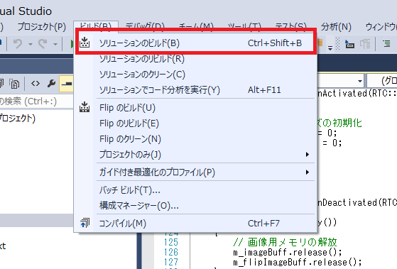
Run build
Select [Build] > [Build Solution] on the Visual Studio to build.
Checking the operation of RobotController component
Connect the created RobotController to the simulator component and check the operation.
Start NameService
Start the name service to register the component reference.
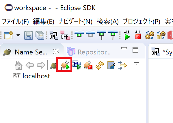
Press the name service start button of RT System Editor to start it.
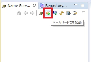
&color(red){NOTE: If omniNames does not start when you click Start Naming Service, make sure the full computer name is set to 14 characters or less.}
Launch the RobotController component
Please start the RobotController component. Run the RobotControllerComp.exe file in the RobotController\build\src\Debug (or Release) folder.
Launching the simulator component
This component starts when you run EXE / RaspberryPiMouseSimulatorComp.exe in the folder where you extracted the file you downloaded earlier (RTM_Tutorial_2018.zip).
Component connection
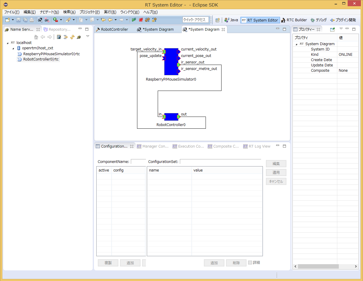
As shown in the figure below, connect the RobotController component and RaspberryPiMouseSimulator component by using RTSystemEditor.
Activate component
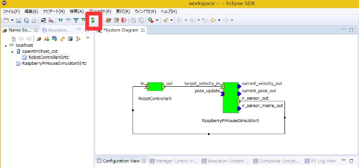
Click the All Activate icon at the top of RTSystemEditor to activate all components. If activated successfully, the component will be displayed in yellow-green as shown below.
Operation check
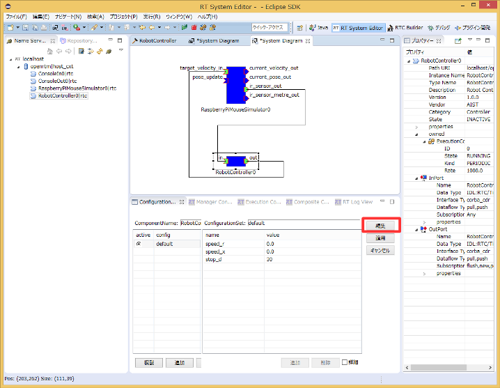
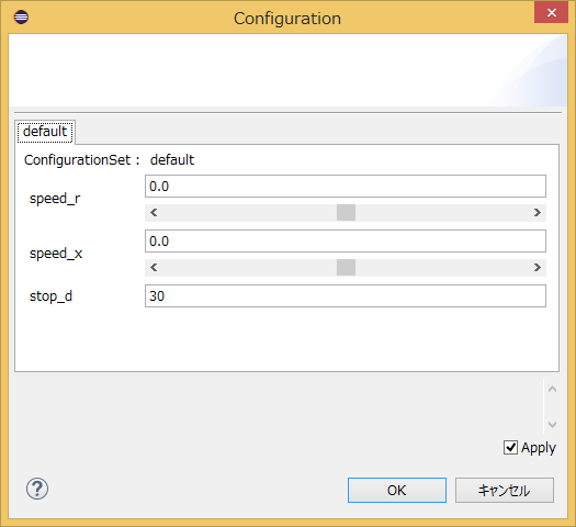
You can change the configuration from the [Edit] button in the configuration view as shown below.
Check if you can operate the [Raspberry Pi] mouse on the simulator by operating the slider.
Operation check on the actual machine
If you have prepared an actual Raspberry Pi mouse on the seminar, you can check the operation on the actual robot, so if you have time to spare, please try it.
The procedure is as follows.
- Power on the Raspberry Pi mouse
- Connect to a Raspberry Pi mouse access point
- Port connection
- Component activation
Turn on the power
The Raspberry Pi mouse has two power switches, one is the Raspberry Pi power switch and the other is the motor power switch.
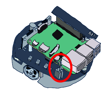
Turn on the power switch on the inside to start the Raspberry Pi.
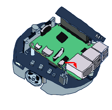
Turning off the power
When turning off the Raspberry Pi, do not turn it off directly from the power switch. Press the button in the middle of the three buttons for a few seconds to start shutting down. The Raspbian shutdown will be completed in about 10 seconds, so turn off the power switch after that.
Connect to an access point
Please refer to the following page for how to connect to the access point.
The SSID and password are printed on the sticker attached to the Rasoberry Pi mouse. First, click on the network icon at the bottom right.
Then select raspberrypi _ *** from the list.
Please input password.
If the network is switched, component registration to the name server and port connection may fail, so close all name servers and components once. If you start it after switching the network, there is no problem, so you do not need to stop it.
To restart the Name Server on the RT System Editor, click the "Start Name Service" button again.
Connecting to the Name-Server
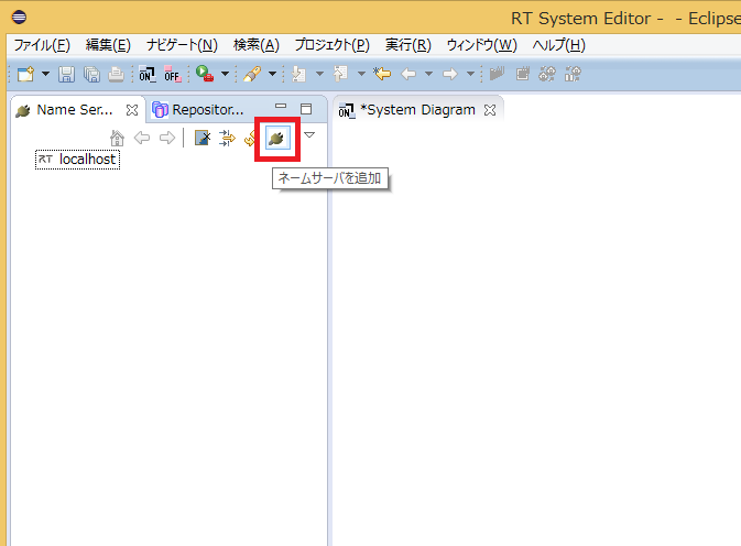
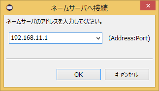
Then add 192.168.11.1 with the [Add Name Server] button in the RTSystemEditor.
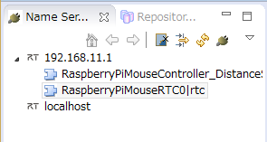
Then you will see the following three RTCs.
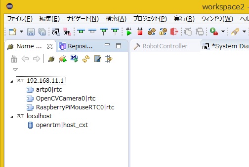
- RaspberryPiMouseRTC
- OpenCVCamera
- artp
RaspberryPiMouseRTC is an RT-Component for controlling Raspberry Mouse, which is being developed in the Robot System Design Laboratory of Meijo University.
Port connection
Connect the RaspberryPiMouseRTC and RobotController components in the RTSystemEditor as follows.
Turn on the motor
Please turn on the power switch of the motor before operation. Be sure to turn off the power of the motor frequently.
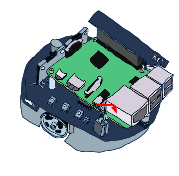
Activation
Then activate the RTC and you will be able to operate the Raspberry Pi mouse.
Tutorial (RTM Seminar, Ubuntu, Part 2)
Introduction
This document describes the procedure for creating RT-Components for controlling the Raspberry Pi mouse on the simulator.
Downloading materials
Please download the materials first.
git clone https://github.com/OpenRTM/RTM_Tutorial
The seminar may be held in an environment where you cannot connect to the Internet. In that case, it is stored in the distributed USB memory.
Simulator
The simulator is developed using a physics engine called Open Dynamics Engine (ODE): http and a drawing library (drawstuff) that comes with ODE. It works if OpenGL works, so it should work in most environments.
You can simulate the following robot Raspberry Pi mouse.
Not only the dynamic calculation and contact response of the Raspberry Pi mouse on the simulator, but also the data of the distance sensor reproduces the values close to those of a real robot.
Raspberry Pi mouse specifications
The Raspberry Pi mouse is an independent two-wheel drive mobile robot sold by RT corp..
| RaspberryPi Mouse Specification | |
| CPU | Raspberry Pi 2 Model B |
| Motor | Stepping motor ST-42BYG020 x2 |
| Motor Driver | SLA7070MRPT x2 |
| Distance sensor | Red LED + Photo-transistor(ST-1K3) x4 |
| Monitor red LEDs | x4 |
| Buzzer | x1 |
| Tact switch | x3 |
| Battery | LiPo3-cells (11.1V) 1000mAh x1 |
RT-Component to be developed
- RobotController Component
An RT-Component to control the robot on the simulator by connecting with the RaspberryPiMouseSimulator Component.
Creating the RobotController Component
An RT-Component which can operate the robot on the simulator with the GUI (slider) and automatically stops when the sensor value exceeds a certain level will be created.

Development process
The development process is as follows.
- Confirmation of development environment
- Determine component specifications
- Creating a source code template with RTC Builder
- Edit source code
- Checking the operation of components
Confirmation of development environment
The following development environment is assumed. Setup the development environment on Linux (assuming Ubuntu 18.04 here).
Installation of dependent libraries
 sudo apt-get install gcc g++
 sudo apt-get install libomniorb4-dev omniidl omniorb-nameserver
 sudo apt-get install python-omniorb-omg omniidl-python
 sudo apt-get install cmake
 sudo apt-get install doxygen
 sudo apt-get install openjdk-8-jdk
 # Switch to java8 for Ubuntu 18.04
 sudo update-alternatives --config java
Installation of OpenRTM-aist
For ubuntu 18.04 (64bit)
 # Installation of all the OpenRTM-aist packages
 wget https://raw.githubusercontent.com/OpenRTM/OpenRTM-aist/master/scripts/pkg_install_ubuntu.sh
 bash pkg_install_ubuntu.sh -l all --yes
 $ hostname
 ubuntu1804 <-- hostname is ubuntu1804
 $ sudo vi /etc/hosts
 127.0.0.1       localhost
 chage this line as follows
 127.0.0.1       localhost ubuntu1804
Installation of CMake
$ sudo apt-get install cmake cmake-gui
Installation of cmake-gui
$ sudo apt-get install cmake-qt-gui
Installation of Code::Blocks
Code::Blocks is a integrated development environment which supports C/C++ languages. Please install it with the following commands.
$ sudo apt-get install codeblocks
If you want to get the latest version, enter the following command.
 $ sudo add-apt-repository ppa:damien-moore/codeblocks-stable
 $ sudo apt-get update
 $ sudo apt-get install codeblocks
Installation of Premake
Required for building ODE.
$ sudo apt-get install premake4 freeglut3-dev
Build RaspberryPiMouseSimulator component
Build the simulator components manually. Enter the following command.
 $ wget https://raw.githubusercontent.com/OpenRTM/RTM_Tutorial_ROBOMECH2019/master/script/install_raspimouse_simulator.sh
 $ sudo sh install_raspimouse_simulator.sh
The seminar may be held in an environment where you cannot connect to the Internet. In that case, start the script in the distributed USB memory.
$ sudo sh install_raspimouse_simulator_usb.sh
Component specifications
The RobotController has an outport that outputs the target speed, an import that inputs the sensor value, and configuration parameters that set the target speed and the sensor value to stop.
| Name of RT-Component | RobotController |
| InPort | |
| Name of InPort | in |
| Type | TimedShortSeq |
| Description | Sensor value |
| OutPort | |
| Name of OutPort | out |
| Type | TimedVelocity2D |
| Description | Target velocity |
| Configuration | |
| Name of configuration parameter | speed_x |
| Type | double |
| Default value | 0.0 |
| Constraints | -1.5<x<1.5 |
| Widget | slider |
| Step | 0.01 |
| Description | The speed of straight-ahead |
| Configuration | |
| Name of configuration parameter | speed_r |
| Type | double |
| Default value | 0.0 |
| Constraints | -2.0<x<2.0 |
| Widget | slider |
| Step | 0.01 |
| Description | The rotational speed |
| Configuration | |
| Name of configuration parameter | stop_d |
| Type | int |
| Default value | 30 |
| Description | The sensor value to be stopped the robot |
About TimedVelocity2D type
We use the TimedVelocity2D type, which is a data type that stores the moving speed of a moving robot on a two-dimensional plane.
     struct Velocity2D
     {
           /// Velocity along the x axis in metres per second.
           double vx;
           /// Velocity along the y axis in metres per second.
           double vy;
           /// Yaw velocity in radians per second.
           double va;
     };


     struct TimedVelocity2D
     {
           Time tm;
           Velocity2D data;
     };
This data type can store the velocity vx along the X axis, the velocity vy along the Y axis, and the velocity va around the Z axis.
vx、vy、va represents the velocity in the robot center coordinate system.
vx is the velocity in the X direction, vy is the velocity in the Y direction, and va is the angular velocity around the Z axis.
For a robot with two wheels mounted on the left and right, such as a Raspberry Pi mouse, vy would be 0 assuming no skidding.
The robot is operated by specifying the straight-ahead speed vx and the rotation speed va.
About distance sensor data
The data of the distance sensor of the Raspberry Pi mouse is designed to output a larger value as the distance to the object gets closer.
| Value from sensor | Actual distance[m] |
| 1394 | 0.01 |
| 792 | 0.02 |
| 525 | 0.03 |
| 373 | 0.04 |
| 299 | 0.05 |
| 260 | 0.06 |
| 222 | 0.07 |
| 181 | 0.08 |
| 135 | 0.09 |
| 100 | 0.10 |
| 81 | 0.15 |
| 36 | 0.20 |
| 17 | 0.25 |
| 16 | 0.30 |
The simulator reproduces this value and outputs it. The RobotController component implements a process that automatically stops when this value exceeds a certain level.
RobotController component template generation
RTCBuilder is used to generate the template for the RobotController component.
Start RTCBuilder
In Eclipse, the folder where you do various tasks is called a "workspace", and as a general rule, all products are stored under this folder. You can create a workspace in any folder that you can access, but this tutorial assumes the following workspace.
- /home/<User name>/workspace
First, start Eclipse with the following command.
$ openrtp
You will first be asked for the location of the workspace, so specify the workspace above.
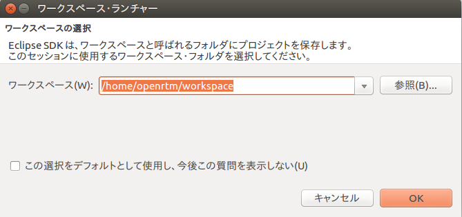
Then, the following Welcome page will be displayed.
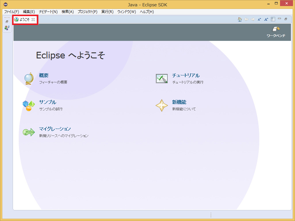
The Welcome page is no longer needed, so click the x button in the upper left to close it.
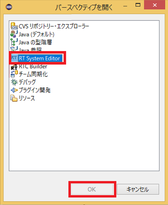
Click the [Open Perspective] button in the upper right.

Select RTC Builder to start RTC Builder. The RTCBuilder icon for Hammer and RT appears in the menu bar.
Create a new project
You need to create a new project in RTCBuilder to create the RobotController component.
Click the Open New RTCBuilder Editor icon in the upper left.

Enter the project name (here, RobotController) to be created in the Project Name field and click the [Finish] button.

A project with the specified name will be generated and added to the Package Explorer.

he RTC profile XML (RTC.xml) with default values is automatically generated in the generated project.
Launch RTC Profile Editor
When RTC.xml is generated, the RTCBuilder editor should open as the workspace associated with this project. If it doesn't start, double-click RTC.xml in Package Explorer.

Profile information input and code generation
First, select the Basics tab on the far left and enter the basic information. In addition to the RobotController component specifications (name) you decided earlier, enter the outline, version, etc. Items with red labels are required items. Others can be the default.
- Module name: RobotController
- Module description: Any (Robot Controller component)
- Version: Any (1.0.0)
- Vendor name: Any
- Module category: Any (Controller)

Then select the Activity tab and specify the action callback to use.
For RobotController component uses the onActivated(), onDeactivated(), onExecute() callbacks. As shown in the figure below, after clicking onAtcivated in (1), check [ON] with the radio button in (2). Just double-clicking the onActivated label toggles [ON] and [OFF]. Follow the same procedure for onDeactivated and onExecute.

In addition, select the DataPort tab and enter the DataPort information. Enter the following based on the specifications you decided above. The variable name and display position are optional and can be left as they are.
- InPort Profile:
- Port name: in
- Data type: TimedShortSeq
- OutPort Profile:
- Port name: out
- Data type: TimedVelocity2D

Then select the Configuration tab and enter the Configuration information based on the specifications you just decided. Constraints and widgets are used to change values in the GUI, such as sliders, spin buttons, and radio buttons, when displaying component configuration parameters in RTSystemEditor.
The straight speed speed_x and the rotation speed speed_r make it easier to operate with the slider.
- speed_x
- Name: speed_x
- Data type: double
- Default value: 0.0
- Constraints: -1.5<x<1.5
- Widget: slider
- Step: 0.01
- speed_r
- Name: speed_r
- Data type: double
- Default value: 0.0
- Constraints: -2.0<x<2.0
- Widget: slider
- Step: 0.01
- stop_d
- Name: stop_d
- Data type: int
- Default value: 30
- Widget: text

Next, select the Language / Environment tab and select the programming language. Here, select C++ (language). In addition, defaults etc. are not set for the language and environment, and if you forget to specify it, an error will occur at the time of code generation, so be sure to specify the language.

Finally, click the Generate Code button on the Basic tab to generate a template for the component.

The generated code set are generated in the workspace folder specified when eclipse is started. You can see your current workspace in File> Switch Workspace ...
Generating the files needed to build with CMake
The code generated by RTCBuilder includes CMakeLists.txt to generate various files required for building by CMake. By using CMake, Visual Studio project files, solution files, Makefiles, etc. can be automatically generated from CMakeLists.txt.
Operation of CMake (cmake-gui)
Use CMake to configure the build environment. First, start CMake (cmake-gui).
$ cmake-gui
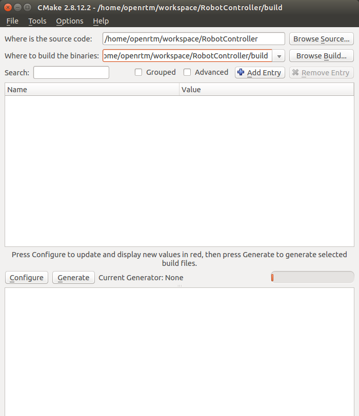
At the top of the window, there are text boxes like the one below, so specify the source code location (where CMakeList.txt is) and the build directory, respectively.
- Where is the soruce code
- Where to build the binaries
The source code location is where the RobotController component source was generated and where CMakeList.txt resides. The default is <workspace directory>/RobotController.
This directory is set by dragging and dropping from Explorer to cmake-gui without any manual input.
The build directory is the place to store project files, object files, and binaries for building. The location is arbitrary, but in this case it is recommended that you specify a subdirectory of RobotController with a descriptive name, such as <workspace directory>/RobotController/build.
| Where is the soruce code | /home/<user name>/RobotController |
| Where to build the binaries | /home/<user name>/RobotController\build |
Once specified, click the [Configure] button below. Then a dialog like the one below will be opened, so specify the type of project you want to generate. This time, specify CodeBlocks -- Unix Makefiles. If you don't use Code::Blocks, use Unix Makefiles.
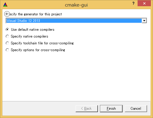
If you don't use cmake-gui, you can generate a Makefiles with the following command.
 $ mkdir build
 $ cd build
 $ cmake .. -G "CodeBlocks - Unix Makefiles"
Click the [Finish] button in the dialog to start Configure. If there are no problems, Configuring done will be output in the log window at the bottom, so click the [Generate] button. If Generating done is displayed, the output of the project file, solution file, etc. is completed.
Note that CMake generates a cache file at the stage of Configure, so if you change the settings or change the environment due to trouble etc., delete the cache with [File]> [Delete Cache] and start over from Configure.
Editing headers and sources
Then double-click RobotController.cbp in the build directory you specified earlier to start Code::Blocks.
Edit the header (include/RobotController/RobotController.h) and the source code (src/RobotController.cpp) respectively. Click RobotController.h, RobotController.cpp from the Project explorer of Code::Blocks to open the edit screen.
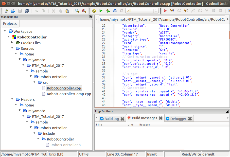
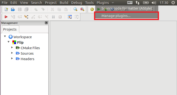
Code::Blocks may become unstable in a 64-bit environment. In that case, disabling the code completion plugin may work.
Please select [Plugins]>[Manage plugins...].
Select [code completion] and click the [Disable] button.
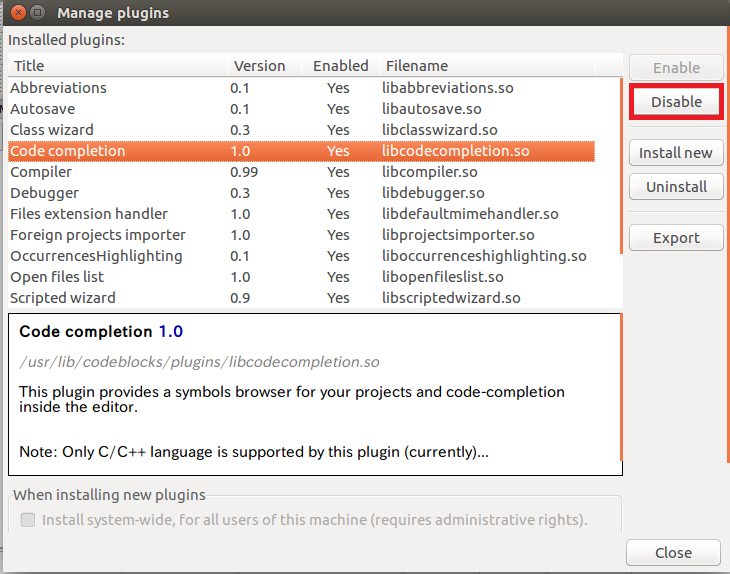
If it doesn't work, try this procedure.
アクティビティ処理の実装
Implementation of activity processing
In the RobotController component, the configuration parameters (speed_x, speed_y) are operated with sliders and the values are output from the outport (out) as the target speed. The value input from import (in) is stored in the variable, and if the value exceeds a certain value, it stops.
The following figure shows the processing contents of onActivated(), onExecute(), and onDeactivated().

Editing the header file (RobotController.h)
Declare the variable sensor_data to temporarily store the sensor value.
   private:
      int sensor_data[4];    // A variable that stores the sensor value
Editing the source file (RobotController.cpp)
Implement onActivated(), onDeactivated(), onExecute() as shown below.
 RTC::ReturnCode_t RobotController::onActivated(RTC::UniqueId ec_id)
 {
         // Initialize sensor vaiables
         for (int i = 0; i < 4; i++)
         {
                 sensor_data[i] = 0;
         }

         return RTC::RTC_OK;
 }
RTC::ReturnCode_t RobotController::onDeactivated(RTC::UniqueId ec_id)
{
// Stopping the robot
m_out.data.vx = 0;
m_out.data.va = 0;
m_outOut.write();
return RTC::RTC_OK;
} RTC::ReturnCode_t RobotController::onExecute(RTC::UniqueId ec_id)
{
// Check if data is arrving
if (m_inIn.isNew())
{
// Read input data from InPort
m_inIn.read();
for (int i = 0; i < m_in.data.length(); i++)
{
// Storing input data
if (i < 4)
{
sensor_data[i] = m_in.data[i];
}
}
}
// Determine if robot is stopped only when moving forward
if (m_speed_x > 0)
{
for (int i = 0; i < 4; i++)
{
// Determine if the sensor value is greater than certain value
if (sensor_data[i] > m_stop_d)
{
//Stop if the sensor value is greater than the set value
m_out.data.vx = 0;
m_out.data.va = 0;
m_outOut.write();
return RTC::RTC_OK;
}
}
}
// If there is no sensor with a value higher than the set value,
// operate with the value of the configuration parameter.
m_out.data.vx = m_speed_x;
m_out.data.va = m_speed_r;
m_outOut.write();
return RTC::RTC_OK;
}Building on Code::Blocks
Run build
Please click [Build] button oon the Code::Blocks to build the project.
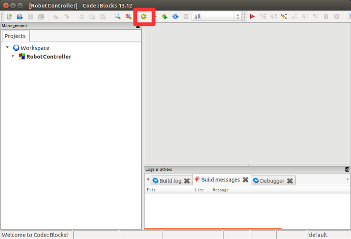
Checking the operation of RobotController component
Connect the created RobotController to the simulator component and check the operation.
Start NameService
Start the name service to register the component reference as follows.
$ rtm-naming
Launch the RobotController component
Please start the RobotController component. Run the RobotControllerComp file in the RobotController/build/src folder.
$ ./RobotControllerComp
Launching the simulator component
After moved to the directory where the RaspberryPiMouseSimulator component is installed ({the directory where the install_raspimouse_simulator.sh script is run}/RasPiMouseSimulatorRTC/build), launch with the following command.
$ ./src/RaspberryPiMouseSimulatorComp
Component connection
As shown in the figure below, connect the RobotController component and RaspberryPiMouseSimulator component by using RTSystemEditor.

Activate component
Click the All Activate icon at the top of RTSystemEditor to activate all components. If activated successfully, the component will be displayed in yellow-green as shown below.
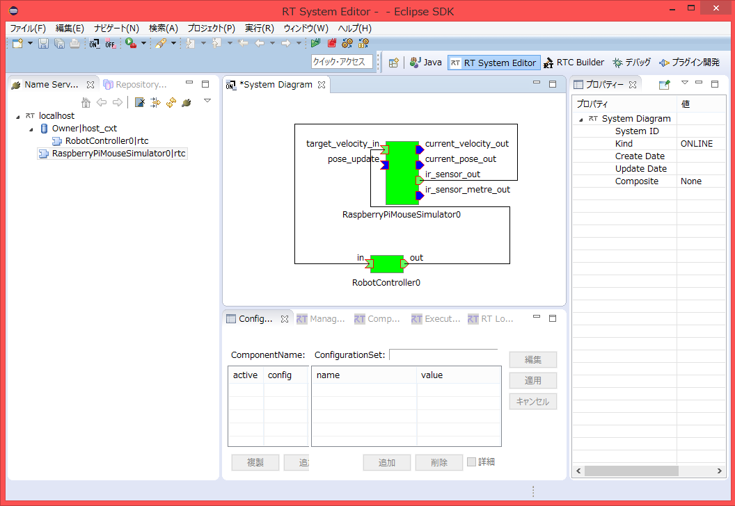
Operation check
You can change the configuration from the [Edit] button in the configuration view as shown below.
Check if you can operate the [Raspberry Pi] mouse on the simulator by operating the slider.

Operation check on the actual machine
If you have prepared an actual Raspberry Pi mouse on the seminar, you can check the operation on the actual robot, so if you have time to spare, please try it.
The procedure is as follows.
- Power on the Raspberry Pi mouse
- Connect to a Raspberry Pi mouse access point
- Port connection
- Component activation
Turn on the power
The Raspberry Pi mouse has two power switches, one is the Raspberry Pi power switch and the other is the motor power switch.

Turn on the power switch on the inside to start the Raspberry Pi.

Turning off the power
When turning off the Raspberry Pi, do not turn it off directly from the power switch. Press the button in the middle of the three buttons for a few seconds to start shutting down. The Raspbian shutdown will be completed in about 10 seconds, so turn off the power switch after that.
Connect to an access point
Please refer to the following page for how to connect to the access point.
If the network is switched, the component registration to the name server and the port connection may fail, so close all the name server and components once. If you start it after switching the network, there is no problem, so you do not need to stop it.
To restart the Name Server on the RT System Editor, click the "Start Name Service" button again.
Connecting to the Name-Server
Then add 192.168.11.1 with the [Add Name Server] button in the RTSystemEditor.
Then you will see the following two RTCs.
RaspberryPiMouseRTC is an RT-Component for controlling Raspberry Mouse, which is being developed in the Robot System Design Laboratory of Meijo University.
Port connection
Connect the RaspberryPiMouseRTC and RobotController components in the RTSystemEditor as follows.
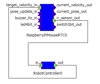
Turn on the motor
Please turn on the power switch of the motor before operation. Be sure to turn off the power of the motor frequently.

Activation
Then activate the RTC and you will be able to operate the Raspberry Pi mouse.
Tutorial (RTM Seminar, Part 3)
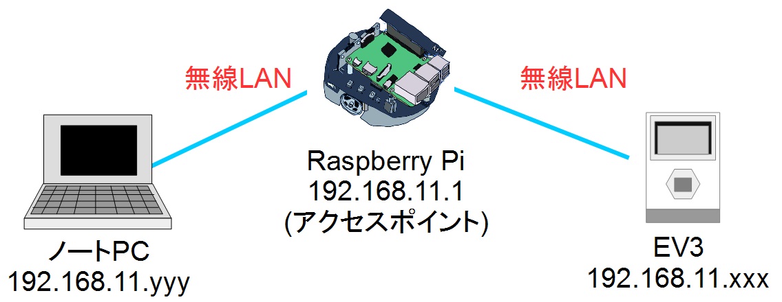
このページではRaspberry PiマウスとLEGO Mindstorms EV3を連携したRTシステムの構築を行います。
Raspberry Piマウスをアクセスポイントとして、ノートPCとEV3をアクセスポイントに接続します。
※Raspberry Piマウスと同じ番号のEV3を使用するようにしてください。
EV3のデバイス
EV3 には以下のデバイスが付属しています。
EV3の組立て
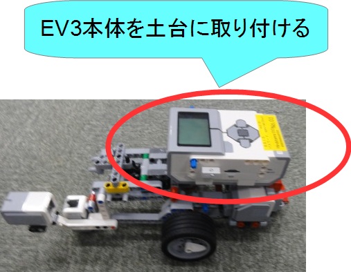
まず、EV3本体を土台に装着します。
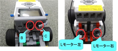
次に25cmケーブルでEV3と左右のLモーターを接続します。
| Lモーター右 | ポート C | 25cmケーブル |
| Lモーター左 | ポート B | 25cmケーブル |
ケーブルに接続するポート、デバイス名は記載してあります。
他のデバイスを取り付ける場合は、チュートリアル(EV3)を参考にしてください。
EV3との接続
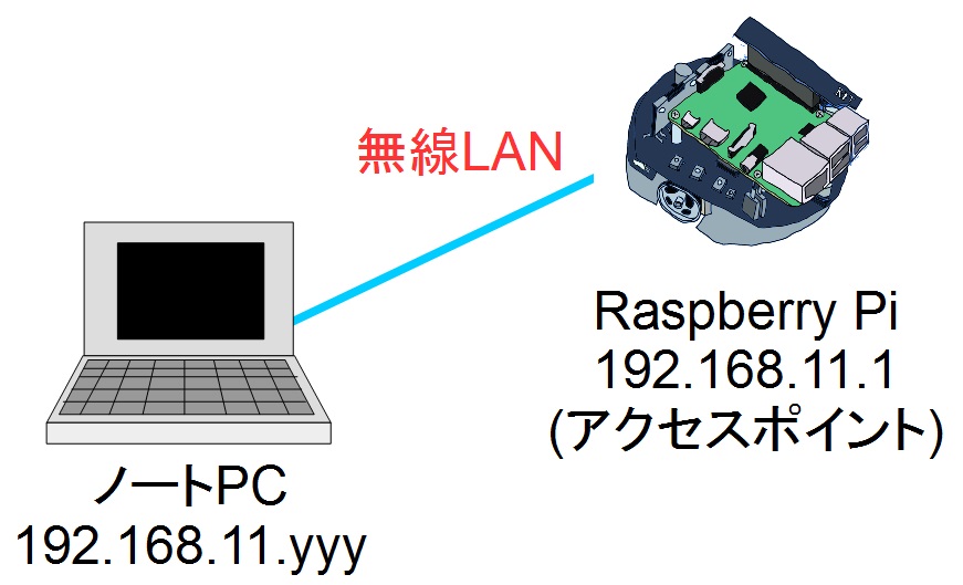
ノートPCとRaspberry Piの接続
第二部の、実機での動作確認まで完了してください。 この時点でノートPCとアクセスポイントのRaspberry Piが接続されているはずです。
EV3の電源の入れ方/切り方
電源の入れ方
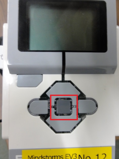
中央のボタンを押せば電源が投入されます。
電源の切り方
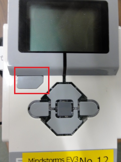
EV3 の電源を切る場合は最初の画面で EV3 本体の左上の戻るボタンを押して「Power Off」を選択してください。
再起動
再起動する場合は最初の画面で EV3 本体の左上の戻るボタンを押して「Reboot」を選択してください。
リセット
ev3dev の起動が途中で停止する場合には、中央ボタン、戻るボタン(左上)、左ボタンを同時押ししてください。画面が消えたら戻るボタンを離すと再起動します。
Raspberry PiとEV3の接続
EV3の電源を投入してください。
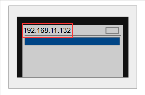
起動後にRaspberry Piに自動接続します。 自動接続できた場合は、EV3の画面左上にIPアドレスが表示されます。 IPアドレスは192.168.11.yyyが表示されます。
ネームサーバー、RTCの起動
EV3の画面上の操作でネームサーバーとRTCを起動します。
EV3 の操作画面から「File Browser」→「scripts」を選択してください。
ネームサーバー、RTCはstart_rtcs.shのスクリプトを実行することで起動します。
 ------------------------------
 192.168.11.yyy
 ------------------------------
         File Browser
 ------------------------------
 /home/robot/scripts
 ------------------------------
 ../
 Component/
 ・・
 [start_rtcs.sh                 ]
 ------------------------------
ネームサーバー追加
RTシステムエディタから、192.168.11.yyyのネームサーバーに接続してください。
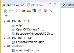
この時点でRTシステムエディタのネームサービスビューにはlocalhost、192.168.11.1、192.168.11.yyyのネームサーバーが登録されています。 192.168.11.yyyのネームサーバーに登録されているRTCの名前はEducatorVehicle1となります。
- localhost
- RobotController0
- 192.168.11.1
- RaspberryPiMouseRTC0
- OpenCVCamera0
- artp0
- 192.168.11.yyy
- EducatorVehicle1
動作確認
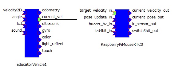
RaspberryPiMouseRTC0(192.168.11.1)とEducatorVehicle1(192.168.11.yyy)をシステムダイアグラム上で接続してください。 EducatorVehicle0の現在の速度出力をRaspberryPiMouseRTC0の目標速度入力に接続することで、EV3の動きにRaspberry Piマウスが追従するようになります。
RTCをアクティベートしてEducator Vehicleの車輪を転がすと、Raspberry Piマウスがそれに合わせて動作します。
自由課題
これで実習は一通り終了ですが、時間が余っている場合は以下のような課題に挑戦してみてください。
EV3のタッチセンサのオンオフでRaspberry Piマウスを操作
EV3のタッチセンサーのオンオフでRaspberry Piマウスを前進後退させるRTシステムを作成します。
タッチセンサー接続
EV3とタッチセンサーを35cmケーブルで接続してください。
| タッチセンサー右 | ポート 3 | 35cmケーブル |
| タッチセンサー左 | ポート 1 | 35cmケーブル |
RTCの作成
以下のような仕様のRTCを作成します。
| コンポーネント名称 | SampleTouchSensor |
| InPort | |
| ポート名 | touch |
| 型 | TimedBooleanSeq |
| 説明 | タッチセンサーのオンオフ |
| OutPort | |
| ポート名 | target_velocity |
| 型 | TimedVelocity2D |
| 説明 | 目標速度 |
| Configuration | |
| パラメーター名 | speed |
| 型 | double |
| デフォルト値 | 0.2 |
| 説明 | タッチセンサがオンの時の直進速度の設定 |
アクティビティでonExecuteを有効にしてください。
SampleTouchSensorのonExecute関数に以下のように記述します。
 RTC::ReturnCode_t SampleTouchSensor::onExecute(RTC::UniqueId ec_id)
 {
     //新規データの確認
     if (m_touchIn.isNew())
     {
         //データの読み込み
         m_touchIn.read();
         //配列の要素数が1以上かを確認
         if (m_touch.data.length() == 2)
         {
             //0番目のデータがオンの場合は直進する指令を出力
             //0番目のデータは右側のタッチセンサに対応
             if (m_touch.data[0])
             {
                 //目標速度を格納
                 m_target_velocity.data.vx = m_speed;
                 m_target_velocity.data.vy = 0;
                 m_target_velocity.data.va = 0;
                 setTimestamp(m_target_velocity);
                 //データ出力
                 m_target_velocityOut.write();
             }
             //1番目のデータがオンの場合は後退する指令を出力
             //1番目のデータは左側のタッチセンサに対応
             else if (m_touch.data[1])
             {
                 //目標速度を格納
                 m_target_velocity.data.vx = -m_speed;
                 m_target_velocity.data.vy = 0;
                 m_target_velocity.data.va = 0;
                 setTimestamp(m_target_velocity);
                 //データ出力
                 m_target_velocityOut.write();
             }
             //オフの場合は停止する
             else
             {
                 //目標速度を格納
                 m_target_velocity.data.vx = 0;
                 m_target_velocity.data.vy = 0;
                 m_target_velocity.data.va = 0;
                 setTimestamp(m_target_velocity);
                 //データ出力
                 m_target_velocityOut.write();
             }
         }
     }
   return RTC::RTC_OK;
 }
RTシステム作成
データポートを以下のように接続後、タッチセンサをオンオフするとRaspberry Piが前進後退します。
ジョイスティックコンポーネントで2台同時に操作
以下GUIジョイスティックでRaspberry Piマウス、EV3を操作するRTシステムを作成します。
ジョイスティックコンポーネント起動
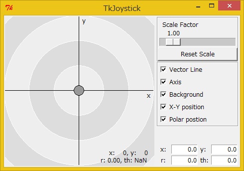
ジョイスティックコンポーネントはOpenRTM-aist Python版のサンプルにあります(TkJoyStickComp.py)。 ジョイスティックコンポーネントは、Windows 8.1の場合は「スタート」>「アプリビュー(右下矢印)」>「OpenRTM-aist 1.2.0」>「Python_Examples」をクリックして、エクスプローラーで「TkJoyStickComp.bat」をダブルクリックして起動してください。
RTC作成
TkJoyStickComp.pyのアウトポートのデータ型はTimedFloatSeq型であるため、TimedVelocity2D型に変換するRTCを作成する必要があります。
以下のような仕様のRTCを作成してください。
| コンポーネント名称 | FloatSeqToVelocity |
| InPort | |
| ポート名 | in |
| 型 | TimedFloatSeq |
| 説明 | 変換前のデータ |
| OutPort | |
| ポート名 | out |
| 型 | TimedVelocity2D |
| 説明 | 変換後のデータ |
| Configuration | |
| パラメーター名 | rotation_by_position |
| 型 | double |
| デフォルト値 | -0.02 |
| 説明 | ジョイスティックのX座標の位置に対する角速度の変化量 |
| Configuration | |
| パラメーター名 | velocity_by_position |
| 型 | double |
| デフォルト値 | 0.002 |
| 説明 | ジョイステックのY座標に対する速度の変化量 |
アクティビティはonExecuteをオンにしてください。
onExecute関数を以下のように編集してください。
 RTC::ReturnCode_t FloatSeqToVelocity::onExecute(RTC::UniqueId ec_id)
 {
     //新規データの確認
     if (m_inIn.isNew())
     {
         //データの読み込み
         m_inIn.read();
         //配列のデータ数確認
         if (m_in.data.length() >= 2)
         {
             //目標速度格納
             m_out.data.vx = m_in.data[1] * m_velocity_by_position;
             m_out.data.vy = 0;
             m_out.data.va = m_in.data[0] * m_rotation_by_position;
             setTimestamp(m_out);
             //目標速度出力
             m_outOut.write();
         }
     }
   return RTC::RTC_OK;
 }
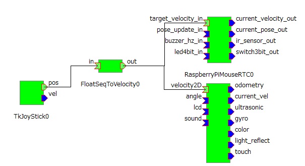
RTシステム作成
以下のようにデータポートを接続してください。
EV3をしゃべらせる
EducatorVehicleRTCのsoundという名前のインポートに文字列(TimedString型)を入力すると、EV3が発声します。
RTC作成
以下のような仕様のRTCを作成してください。
| コンポーネント名称 | SpeechSample |
| OutPort | |
| ポート名 | out |
| 型 | TimedString |
| 説明 | 発話する文字列 |
アクティビティはonExecuteをオンにしてください。
onExecute関数を以下のように編集してください。
 RTC::ReturnCode_t SpeechSample::onExecute(RTC::UniqueId ec_id)
 {
     std::cout << "Please input: ";
     std::string ret;
     //文字入力
     std::cin >> ret;
     //データに格納
     m_out.data = CORBA::string_dup(ret.c_str());
     setTimestamp(m_out);
     //データ出力
     m_outOut.write();

   return RTC::RTC_OK;
 }
文字列(const char*)をデータポートで出力する際はCORBA::string_dup関数で文字列をコピーする必要があります。
m_out.data= CORBA::string_dup("abc");RTシステム作成
以下のようにデータポートを接続してください。
マーカーの追従
Raspberry Piマウスを起動すると、OpenCVCameraコンポーネントとarptコンポーネントが起動します。 OpenCVCameraコンポーネントは画像を取得するコンポーネント、artpコンポーネントは画像データからマーカの位置姿勢を計算して出力するコンポーネントです。
Raspberry Piマウスがマーカーに追従するRTシステムを作成します。
カメラの装着
まずはカメラをRaspberry Piマウスに装着します。
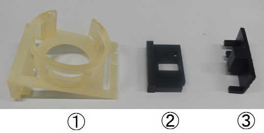
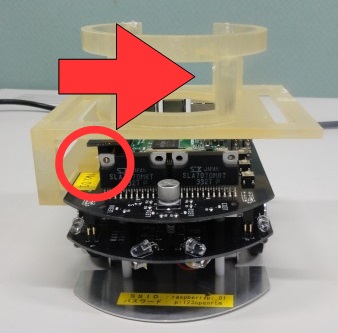
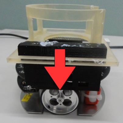
以下の土台部品をRaspberry Piマウスに取り付けていきます。
部品①をRaspberry Piマウスの上部に装着してください。 左から押し込むようにして取り付けます。
この時、左側の突起がプレートを挟むように取り付けてください。
部品②を部品①の左側に上から差し込んでください。
部品③を左側から部品②に差し込んでください。
最後にカメラを搭載して、USBケーブルをRaspberry Piに差し込んだら完成です。
RTC作成
以下の仕様でRTCを作成してください。
| コンポーネント名称 | testARToolKit |
| InPort | |
| ポート名 | marker_pos |
| 型 | TimedPose3D |
| 説明 | マーカーの位置 |
| OutPort | |
| ポート名 | target_vel |
| 型 | TimedVelocity2D |
| 説明 | ロボットの目標速度 |
| Configuration | |
| パラメーター名 | x_distance |
| 型 | double |
| デフォルト値 | 0.5 |
| 説明 | マーカーまでの目標距離(X軸) |
| Configuration | |
| パラメーター名 | y_distance |
| 型 | double |
| デフォルト値 | 0 |
| 説明 | マーカーまでの目標距離(Y軸) |
| Configuration | |
| パラメーター名 | x_speed |
| 型 | double |
| デフォルト値 | 0.1 |
| 説明 | X軸方向移動速度 |
| Configuration | |
| パラメーター名 | r_speed |
| 型 | double |
| デフォルト値 | 0.2 |
| 説明 | 回転方向移動速度 |
| Configuration | |
| パラメーター名 | error_range_x |
| 型 | double |
| デフォルト値 | 0.1 |
| 説明 | X軸方向目標距離の許容範囲 |
| Configuration | |
| パラメーター名 | error_range_y |
| 型 | double |
| デフォルト値 | 0.05 |
| 説明 | Y軸方向目標距離の許容範囲 |
アクティビティはonExecuteをONにしてください。
onExecuteを以下のように編集してください。
 RTC::ReturnCode_t testARToolKit::onExecute(RTC::UniqueId ec_id)
 {
     //新規データの確認
     if (m_marker_posIn.isNew())
     {
         m_target_vel.data.vx = 0;
         m_target_vel.data.vy = 0;
         m_target_vel.data.va = 0;

         //データの読み込み
         m_marker_posIn.read();
         //マーカーの位置(X軸)が目標距離(X軸)よりも大きい場合
         if (m_marker_pos.data.position.x > m_x_distance + m_error_range_x/2.0)
         {
             m_target_vel.data.vx = m_x_speed;
         }
         //マーカーの位置(X軸)が目標距離(X軸)よりも小さい場合
         else if (m_marker_pos.data.position.x < m_x_distance - m_error_range_x/2.0)
         {
             m_target_vel.data.vx = -m_x_speed;
         }
         //マーカーの位置(Y軸)が目標距離(Y軸)よりも大きい場合
         else if (m_marker_pos.data.position.y > m_y_distance + m_error_range_y/2.0)
         {
             m_target_vel.data.va = m_r_speed;
         }
         //マーカーの位置(Y軸)が目標距離(Y軸)よりも小さい場合
         else if (m_marker_pos.data.position.y < m_y_distance - m_error_range_y/2.0)
         {
             m_target_vel.data.va = -m_r_speed;
         }
         setTimestamp(m_target_vel);
         //データ書き込み
         m_target_velOut.write();
     }
   return RTC::RTC_OK;
 }
RTシステム作成
データポートを以下のように接続してください。
RTCをアクティベートしてカメラの前でマーカーを動かして、Raspberry Piマウスが移動するかを確認してください。
Tutorial (RTM Seminar, Part 4)
はじめに
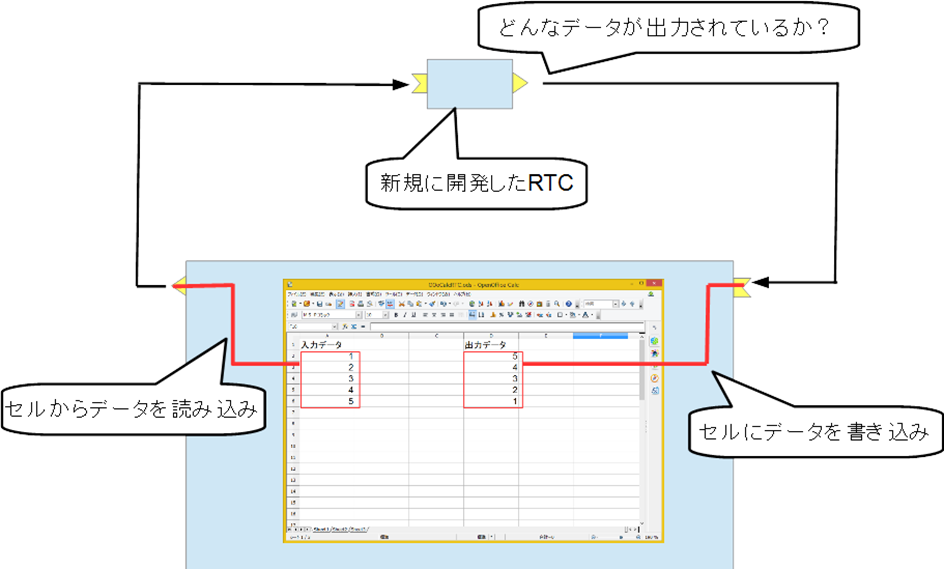
このページではLibreOffice Calc用RTCによるRTCの動作確認手順について説明します。 Calcのセルの値をInPortに入力、OutPortの出力した値をセルに表示することで対象RTCの挙動を確認できます。
RTM講習会ではUSBメモリでポータブル版LibreOfficeとRTCを配布します。 Windowsで実行できます。 UbuntuはPython3用のomniORBのパッケージがないため実行できません。講習会ではノートPCを貸し出します。
この実習では第2部で作成したRobotControllerコンポーネントを使用します。
LibreOfficeとは?
表計算、パワーポイント、ワープロ機能等を提供するオフィススイートです。 フリーソフトとして公開されており、今回の講習会では以下のポータブル版を使用します。
LibreOffice Calc用RTCの起動
配布したUSBメモリ内のポータブル版LibreOffice\run_CalcRTC.batを実行します。
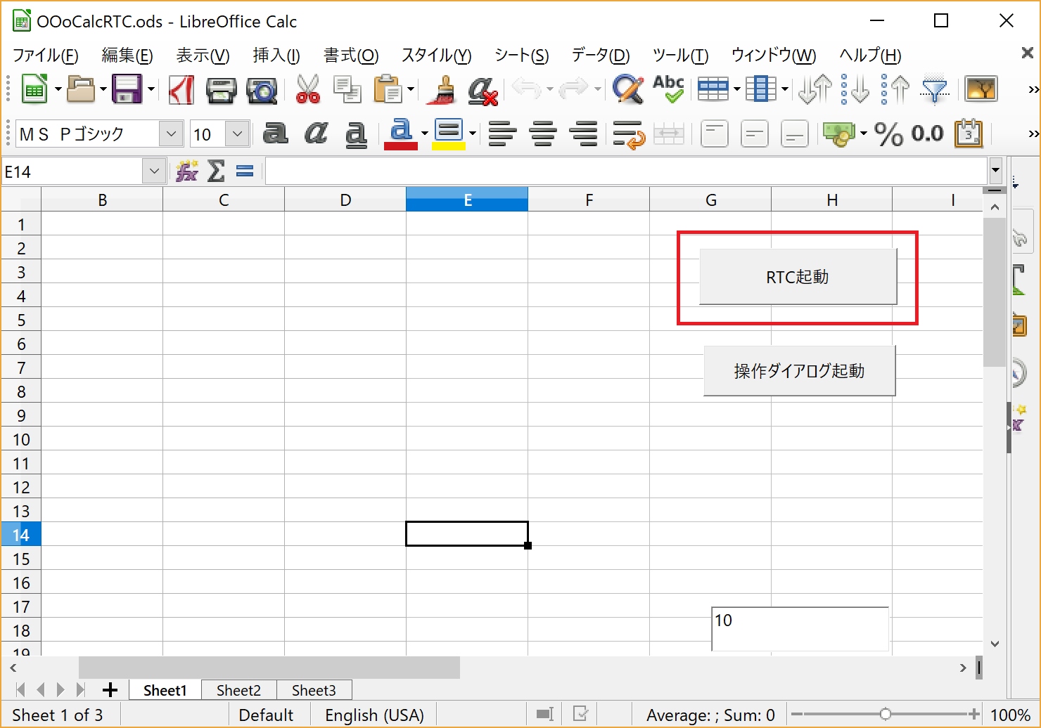
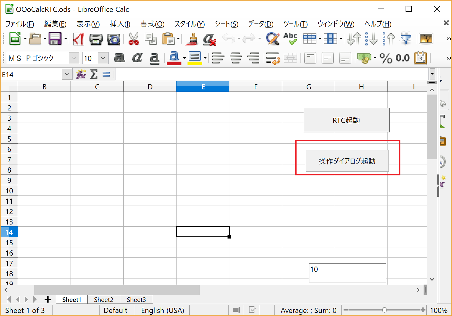
LibreOffice Calcが起動するため、RTC起動ボタンをクリックすることでOOoCalcControlというRTCを起動します。
OutPortの接続
RobotControllerのOutPortと接続し、Calcで出力データの確認ができるようにします。 Calcの操作ダイアログ起動ボタンをクリックしてください。
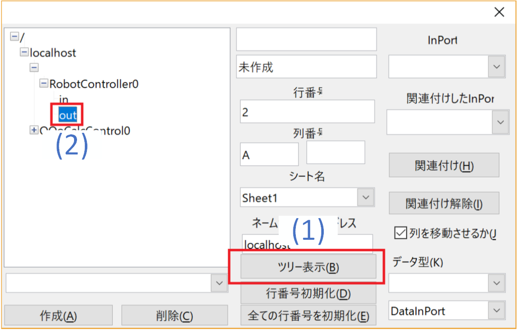
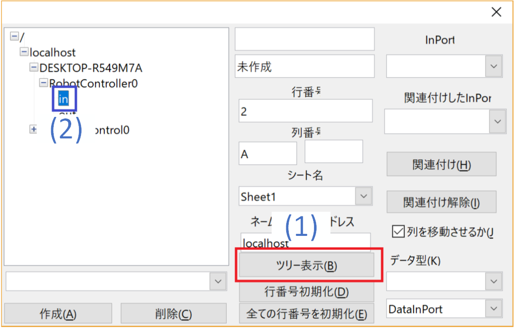
まずは出力データを確認するOutPortと接続します。 ツリー表示ボタンを押下してネームサーバーに登録されたRTCのポート一覧を表示後、ツリーからRobotController0のoutを選択します。
次に一部設定を変更します。
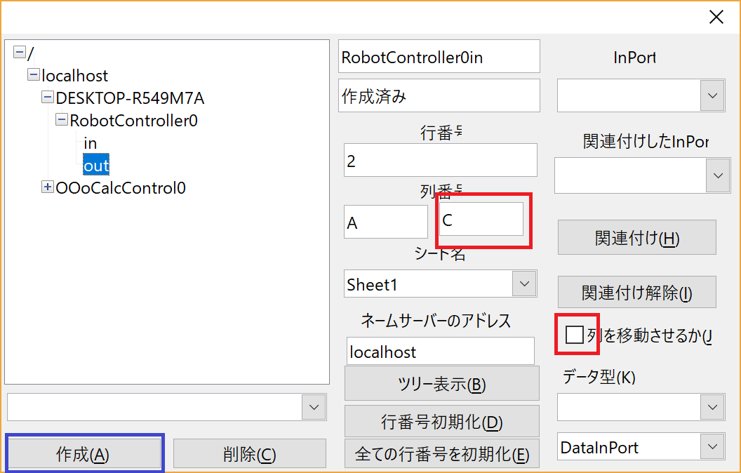
列を移動させるのチェックを外してください。 このチェックが有効の場合、データを受信する度にセルの位置が移動するモードで動作します。 グラフに描画する場合は位置が移動するモードを使用しますが、今回は単純に値を確認したいだけのためチェックを外します。
列番号の右のボックスにCと入力してください。 これで2行目のA~C列のセルにOutPortの出力データを表示するようになりました。
設定完了後、作成ボタンを押してください。
OutPortの動作確認
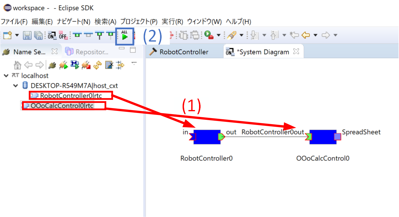
RT System Editor上でRTCをアクティブ化して動作を確認してください。
この状態でコンフィギュレーションパラメータを操作してCalcのセルの値が変化するかを確認してください。
InPortの接続
RobotControllerのInPortと接続し、Calcからデータの入力を行うようにします。
ツリー表示ボタンを押下してネームサーバーに登録されたRTCのポート一覧を表示後、ツリーからRobotController0のinを選択します。
次に一部設定を変更します。
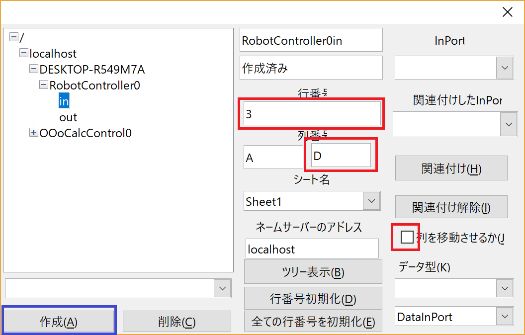
列を移動させるのチェックを外してください。
列番号の右のボックスにDと入力してください。 これで3行目のA~C列のセルにOutPortの出力データを表示するようになりました。
設定完了後、作成ボタンを押してください。
InPortの動作確認
RT System Editor上でRTCをアクティブ化して動作を確認してください。
この状態でコンフィギュレーションパラメータで前進する速度をOutPortから出力するように操作してください。 その後、Calcの3行目のA~C列のセルに31以上の値を入力するか、30以下の値を入力するかで動作が変化するかを確認してください。
